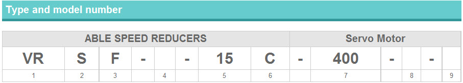
ABLE Reducer Model
ABLE Reducer Model
S:Input part
K:Coupling (Straight shaft, with keyway) D-cut is available only for K type.
A:Adapter type (Please contact us for the details.)
Installation and output shaft direction
F: Flange type, Mounting free
D: With D-fl ange type, Mounting free

Reducer specifi cations
Blank: Standard backlash
LB : Low backlash
PB : Precision backlash
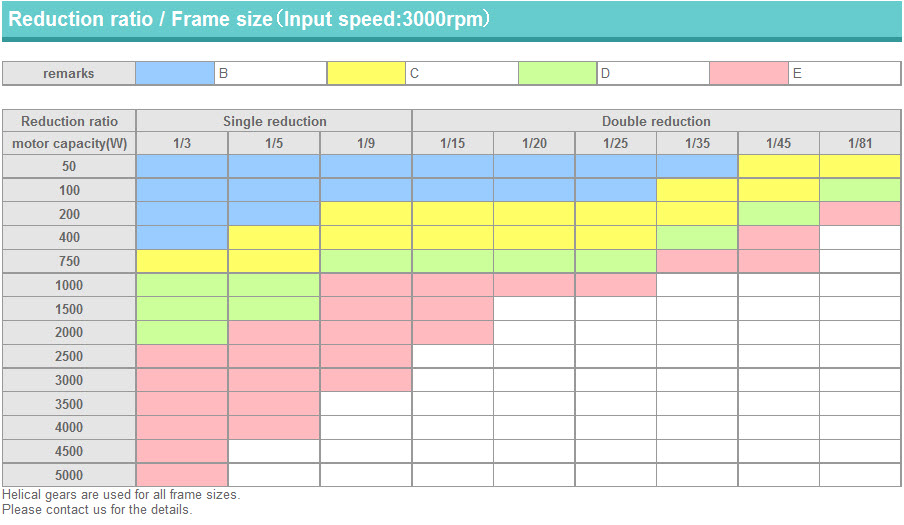
Reduction ratio
Single reduction 3, 5, S9
Double reduction 15, 20, 25, 35, 45, 81
Frame size B,C,D,E
Applicable servo motor capacity (W)
Servo motor manufacturer
Model number of servo motor

*Please specify the servo motor's model number.

Remove the rubber cap and turn the input shaft until the cap screw is seen. Make sure the cap screw is loosened.
Carefully insert the Servo motor shaft into the input shaft. (It should be inserted smoothly.) Make sure the Servo motor shaft and input shaft are properly aligned.
Install the Servo motor to the reducer and tighten the bolts to the proper torque. See Table 1.
Tighten the cap screw of the input shaft with a torque wrench to the proper torque. See Table 2.
Reinstall the rubber cap.

TABLE1
Motor installing bolt Tightening torque
N,m kgf,cm
M3 1.0 10
M4 3.0 30
M5 5.8 60
M6 9.8 100
M8 19.6 200
M10 39.2 400
M12 68.6 700
M16 168 1650

TABLE2
Cap screw Tightening torque
N,m kgf,cm
M3 1.5 15
M4 3.5 35
M5 7.1 71
M6 12 120
M8 30 300